

| Elliott Sound Products | Project 09 |
24 dB/Octave 2/3-Way Linkwitz-Riley Electronic Crossover
Rod Elliott - ESP
Last Updated 30 May 07
Please Note: PCBs (revision B) are available for this project. Click the image for details.The Linkwitz-Riley filter featured here has (almost) perfect phase-coherency, with no peaks or dips at the crossover frequency. The design is adaptable to 2-way or 3-way (or even 4-way) operation, and all formulas are provided below (or use the ESP-LR component calculator program).
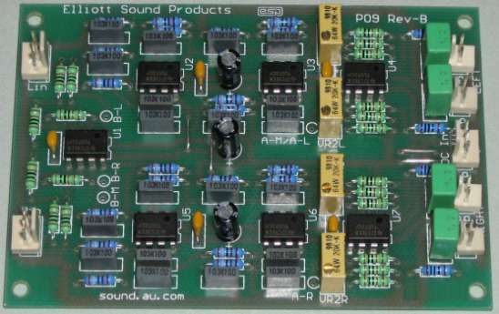
Please note that the PCB version of the P09 crossover is a stereo 2-way design, and has balanced input buffers (unbalanced also available), high and low pass filters, level controls and output buffers for each channel. Each output buffer is configured for variable gain to allow your system to be set up correctly. The suggested power supply is the P05 Rev-B, which also has an auxiliary output suitable for operating muting relays (see below for reasons you may want to include muting).
Figure 1A - Stereo Version of a 2-Way LR Crossover
Figure 1A shows the general concept for a full stereo version, with two identical filter sections (but without balanced inputs). With the component values shown, these have a crossover frequency of 310Hz (refer to the article on Bi-Amping to see the reason for my choice of frequency). This unit will provide a completely flat frequency response across the crossover frequency, with the signal from both filters remaining in phase at all times.
The 2-Way unit is separated into 3 sections per channel ...
It is important with both versions that the filters are properly matched, both within the individual filters, and between channels. While small variations between channels will not be audible, if the high and low pass sections are not accurately matched, then phase and amplitude errors will result.
Figure 1B - 3-Way Mono LR Crossover (2 Needed for Stereo)
Figure 1B shows the way to connect a 3-Way crossover. This unit will produce excellent results, with good phase coherency and a flat response across the entire frequency band.
I know the circuits look complicated, but each is basically repetition of a common circuit block - the filter section. Since the opamps are all used as unity gain buffers, the use of premium devices is not really essential, so the TL072 type would be quite serviceable in this role. Needless to say, if you want to use better devices (even discrete opamps) you can easily do so. Make sure that any device used is stable for unity gain - this is not always the case with some devices, especially when external compensation is used. In this case, use the manufacturer's recommended value of stability cap for unity gain operation.
 |
Power supply connections (and bypass capacitors) have not been shown, but the diagram shows the standard connections for a dual opamp. The IC is viewed from the top. The +/-15V power supply described (see Project 05 - Power Supply For Preamps) is suitable for this crossover as well. For dual opamps, power is connected to Pin 4 (-ve) and Pin 8 (+ve). |
NOTE: Only one channel is shown for the 3-Way - for a stereo setup, two identical filter circuits are required.
As can be seen, the 3-Way unit is separated into 4 sections ...
If it helps, I have included a block diagram that may make things clearer. This is shown below, and has all the sections for a 3-way crossover network. Again, this is mono, so two complete blocks are used for a stereo system.
Figure 1C - Block Diagram of 3-Way Crossover
Frequencies shown are for reference only, and are the same as described above. Naturally, these may need to be changed to suit your application.
The frequency responses of each section are shown below, note that the crossover frequency is at the -6dB point, and not at the traditional -3dB frequency. This is an important difference between a Butterworth and Linkwitz-Riley filter, and allows the signals to be in phase across the audio band, regardless of which filter section they are being passed by. The summed output of this filter is flat, there are no peaks or dips, and no phase reversals are produced (unlike Butterworth filters).
A simple test with any electronic crossover is to connect a 10k resistor to each output, and join the other ends together. Run a frequency sweep from an audio oscillator into the input, and observe the output level at the output of the resistor summing network. Most crossovers exhibit a 3dB increase at the xover frequency, and drop back to the reference level about an octave or so each side. This is a less than ideal situation, since in most cases a similar effect will occur from the speaker's summed acoustical output - assuming that the drivers are "time aligned" so the output of each is in phase (acoustically speaking) at the crossover frequency. If time alignment is not done, and the physical distance difference between speaker voice coils is large (more than 0.1 wavelength of the frequency concerned), then other acoustical differences caused by phase will tend to overshadow any anomaly in the crossover network.
Figure 2 - Frequency Response of 3-Way Linkwitz-Riley Crossover Network
Frequency response is shown from 20Hz to 20kHz. Insertion loss is 0dB, since there is no gain or loss introduced by the filters in their pass-band. The crossover points are defined by the -6dB points of each filter, and are at 310Hz and 3.1kHz (as expected from the above schematics).
If you are going to use the crossover, you will need some way of equalising the levels from each output to match the power amp sensitivity and speaker efficiency. I have had several requests for this, so the circuit for a suitable buffer is shown in Figure 3. There is nothing special about it, but it is designed to give a gain of 2 to allow maximum flexibility, and ensures that the impedance of the pots does not cause any high frequency loss with long interconnects.
Figure 3 - Buffer Stage. One Per Output Needed
These buffers should use high quality opamps, and they are included on the PCB.
Several people (including me) have found that the crossover unit has a short 'chirp' or 'snap' (depending on the opamp characteristics) as power is removed, and this may be accompanied by some DC swing. If you use the new version of the P05B preamp power supply, the auxiliary output can be used to activate a 6-pole relay (or as many smaller relays as needed) to short all outputs to earth when there is no power. The normally closed contacts simply short the outputs to ground, and when power is applied the short is removed. P05 (Rev-B) boards have a power-on delay and a loss of AC detector that will mute the crossover for a few seconds at power-on, and almost immediately when power is turned off.
Because all common opamps have short circuit protection, this will not cause any damage, and current is limited further by the 100 ohm output resistors.
As you can see from the main circuit diagram, a 4th order Linkwitz-Riley would be difficult to make into a variable network, due to the large number of resistors which need to change. Use of multi-ganged potentiometers is discouraged, because of the matching requirements. Sufficiently accurate 8-gang pots are unlikely to be readily available!
(1) R = 1 / (2 * π * 1.414 * f * C)Where R = resistance in Ohms, π = 3.14159, 1.414 is √2, f = frequency in Hertz and C = capacitance in Farads
(2) C = 1 / (2 * π * 1.414 * f * R)
(3) f = 1 / (2 * π * 1.414 * R * C)
(1) This assumes that you have selected the capacitance first, which is the most sensible, since they are available in fewer different values in each decade than resistors. Capacitors follow the "E12" series, which has 12 values per decade, so:
1.0, 1.2, 1.5, 1.8, 2.2, 2.7, 3.3, 3.9, 4.7, 5.6, 6.8, 8.2, 10These are multiplied by 10, 100 (etc), to obtain all the values from 1nF - 10nF, 10nF - 100nF, and 100nF - 1uF. Values above 1uF and below 100pF are generally not as readily available in all values, and should be avoided for this design, since very large or very small values will create impedances which are too difficult to handle. Very low values of capacitance mean that even small amounts of stray capacitance on PCB tracks or in wiring will create errors. Large values of capacitance will imply low impedances, which opamps may not be able to drive without excessive distortion or clipping.
(2) Is the least useful, since the range of capacitor values is only half that of 1% resistors. Really strange values can be assured, which will require parallel combinations of smaller caps - messy.
(3) Is useful to check that the components selected will give you the frequency that you first thought of, or something reasonably close after standard component values have been substituted for the theoretical values you will get with the calculation.
The calculator program is far easier and more fun, too. (Of course I like it - I wrote it!)
Capacitor values need to be accurate - the standard offering is +/-10%, which is not really good enough. If you have (or can get access to) a capacitance meter, simply buy more than you need (they are inexpensive), and select the values to be within 2% or better if possible. My experience is that the tolerance of most MKT and MKP caps is actually better than that quoted, but you do need to check!
The easiest way to get the "2C" value is to use two capacitors in parallel, each of value "C".
Resistor values also need to be accurate, and 1% metal film resistors are perfectly acceptable. These are generally available in the E24 series (24 values per decade), allowing a much wider choice of values. Both the E12 and E24 series values are available in the Component Calculator (Help-Preferred Values) for reference. In some shops (oh, really?) you might even be able to get resistors in the E48 or E96 range - these offer an almost limitless range of possibilities (48 or 96 values per decade - awesome!), just don't count on it.
The completed Linkwitz-Riley component calculator is available for you to download. It includes the circuit diagrams for both the high-pass and low-pass sections, and has the following features:
The program requires the Microsoft VB6 run-time library, which can be obtained from Microsoft's web site if it is not installed on your machine. Note that the program is 32-bit, so it won't run on pre Win98 operating systems. The following is a guide as to where the DLL should be installed ...
| Operating System | VB6 Support File Location | |
| Windows95 | Not supported | |
| Windows98 | c:\windows\system | |
| WindowsNT | c:\winnt\system32 | |
| XP | c:\windows\system32 | |
| Vista | Should be pre-installed |
In all cases, the above assumes that the C: drive is the installation drive. This will usually be the case, but some installations may differ.
Note that although all care has been taken to ensure the file is virus free, ESP cannot absolutely guarantee that this is the case - I don't appear to have any viruses on my machine, but one cannot be too careful. As with all executable downloads, use your own virus scanner to check it before execution.
 Projects Index
Main Index
Projects Index
Main Index
| Copyright Notice. This article, including but not limited to all text and diagrams, is the intellectual property of Rod Elliott, and is Copyright © 1999-2007. Reproduction or re-publication by any means whatsoever, whether electronic, mechanical or electro-mechanical, is strictly prohibited under International Copyright laws. The author (Rod Elliott) grants the reader the right to use this information for personal use only, and further allows that one (1) copy may be made for reference while constructing the project. Commercial use is prohibited without express written authorisation from Rod Elliott. |
Updated 15 Sep 06 - minor corrections and additions./ 06 Sep 05 - Added block diagram, info reformat./ 13 Aug 01- update, and linked new calculator./ 25 Mar 2000 - Added Buffer Amp./ 26 Oct 1999 - Modified circuit to reduce high frequency phase errors./ 20 Nov 1999 - added resistors to filter outputs on all drawings./ 30 May 07 - Changed page to suit Rev-B boards